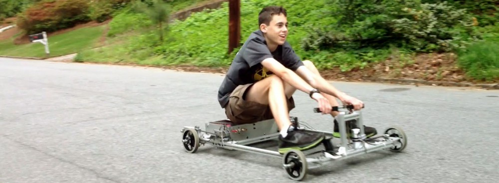
The Go Cart is finally powered up and running!
I wasn’t going at full speed due to the approaching car as you might notice…
Before I go any farther I have to extend a massive THANK YOU to Ryobi for providing many of the tools that made this project possible.
I have been a little busy recently which is why this build log – I will continue to update with additional photos and videos – is all one page.
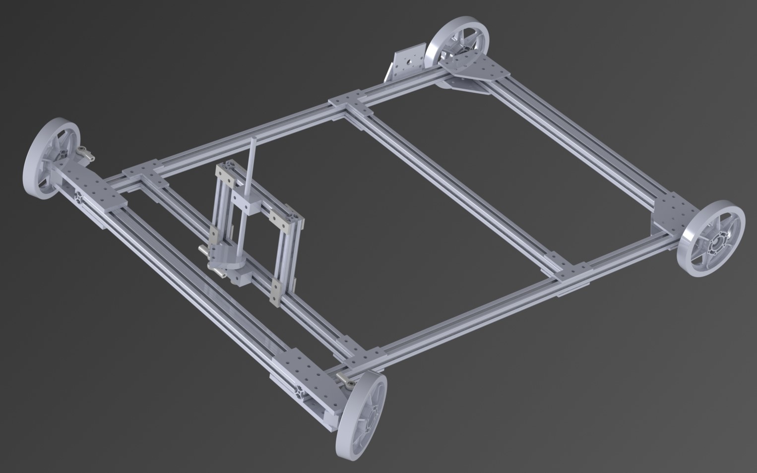
To recap I started the project by creating a CAD model for the bare bones frame of the cart.
I was able to Waterjet most of the brackets for the 80/20 which saved me a lot over having to by $7 brackets. Thanks GT Invention Studio.
Next came a lot of boxes…

From McMaster Carr
- 80/20 (1 inch)
- Nuts and Bolts
- Aluminum Bars/Blocks (either 3/16 inch or 1 inch thick)
- Bearings and other assorted hardware.
- Hella Switch
- Terminal Block
From Hobbyking
- 2x Turnigy Aerodrive SK3 – 5065-236kv Brushless Outrunner Motor
- 4x 4S1P LiPo (best Watt/Dollar rate)

- Battery Charger and Power Supply
- Noodle wire, Shrink Tube, a LiPo charging back and other electronic goodies.
From Amazon
From TNC Scooters
From AndyMark
- Sprockets (currently a 9:42 reduction)
- #25 Chain and connector links
From Ebay
- 24V 500W Motor Controllers (no hall)
A note about the motor controllers. While they might seems sketchy (yes they are) so far they have worked great. The only downside is that they require the wheels to be spinning ~1mph from the motor controllers to kick in and start moving. They also max out at 4700rpm. Charles Guan provides a fantastic explanation of how these things work and why you should buy them if you don’t yet have the technical expertise of using a Kelly controller
I had a number of parts like wheels, collars, some 1″x2″ 80/20 from a disbanded FIRST team.
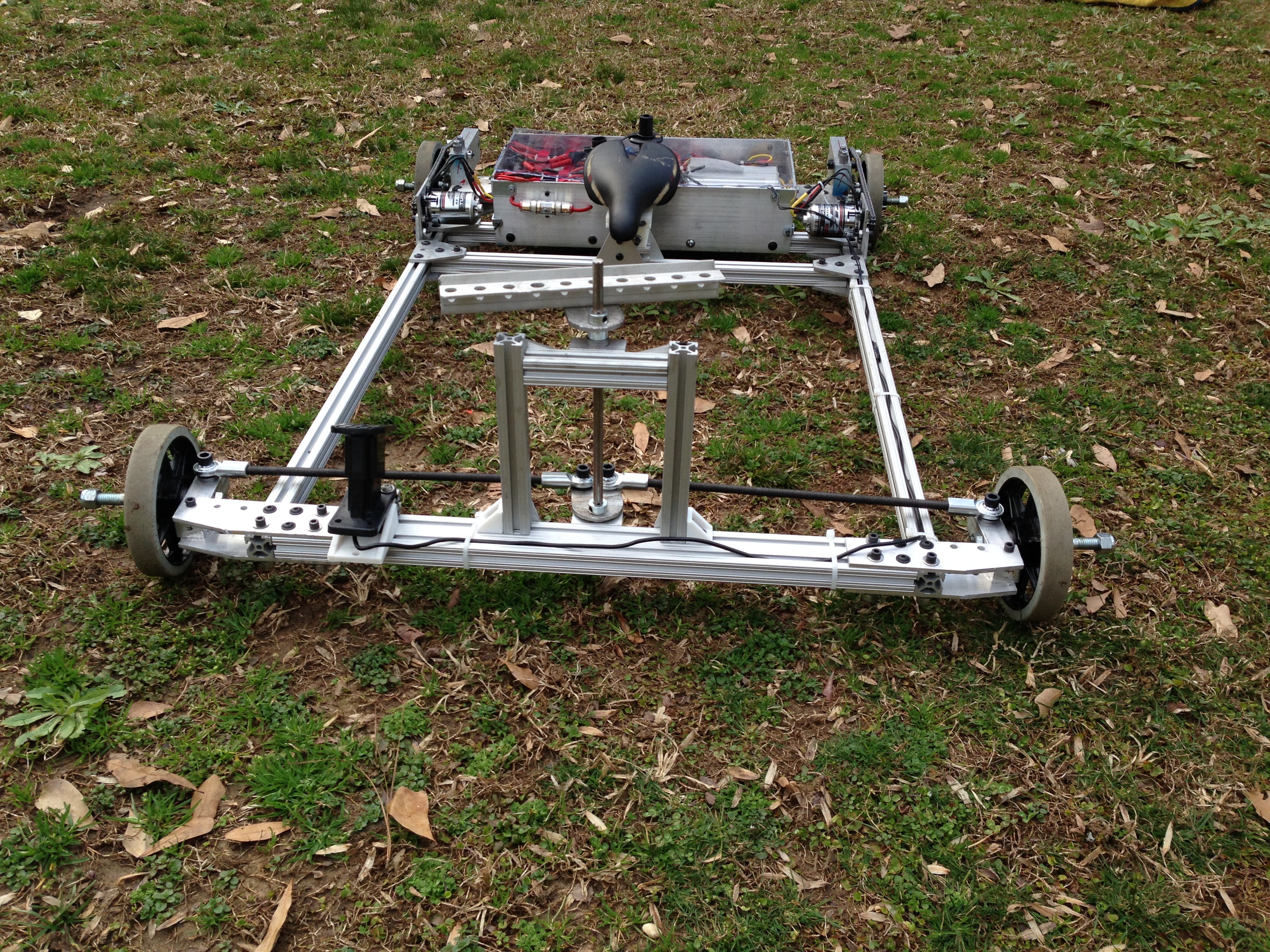
Once I had all of the parts it was time to build the frame which I talked about here. It was not terribly complicated as T-Sloted framing bolts together quite nicely.
Finishing up the Frame
I still needed to add an enclosed area to house all of the electronics and a seat. The seat is a bike seat that I had lying around mounted to some 80/20.
Meanwhile the frame is built from 3/16 inch aluminum plate. Its a little excessive in terms of strength, but at least none of the electronics are going to get damaged.
Also as you may have noticed from the video the cart is not the most comfortable thing to ride around for long periods so I need to raise the seat up and angle the throttle so my foot can press it. Right now you have to press down on it toward the ground instead of pressing forward in the direction of travel.
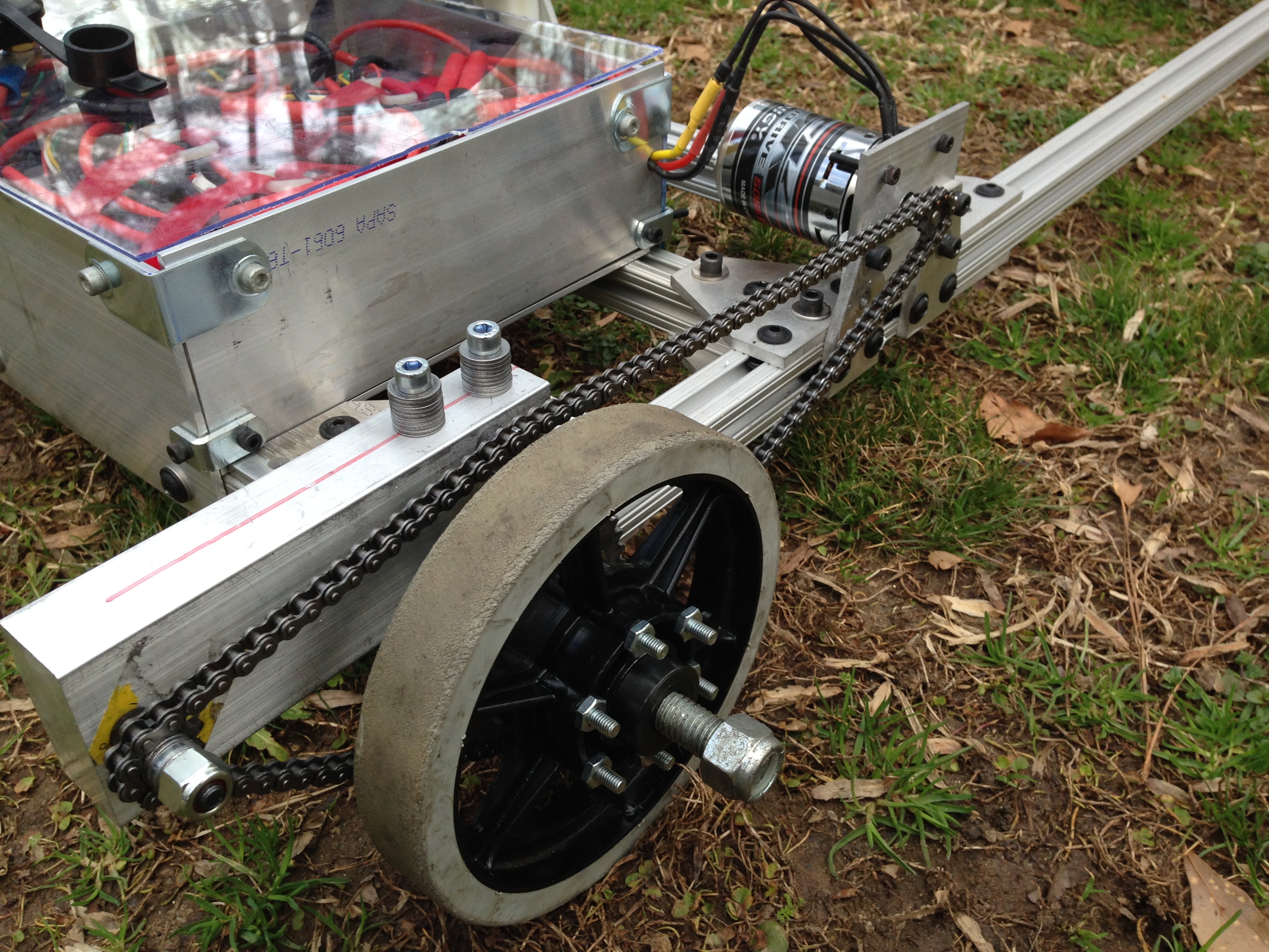
WHEELS, SPROCKETS AND CHAIN!
What should have been the one of the easier parts of the go cart turned out to be quite annoying. The reason is because the #25 chain will not wrap all of the way around the sprocket due to the distance between the teeth. Instead I had to attach 2 more sprockets to ensure that the chain only ran along a limited portion of the sprocket.
Putting the chain itself together was not a problem because I could adjust the distance of the motor to main sprocket since the motor was mounted to a plate on 80/20 so it could slide up and down.
Assembling the Electronics
Big globs of solder are required so make sure you have a soldering iron handy with a big tip (no SMD parts here). Then cover everything with Shrink Tube. I ordered a bunch of sizes from Hobbking because its so cheap and used a hair dryer.
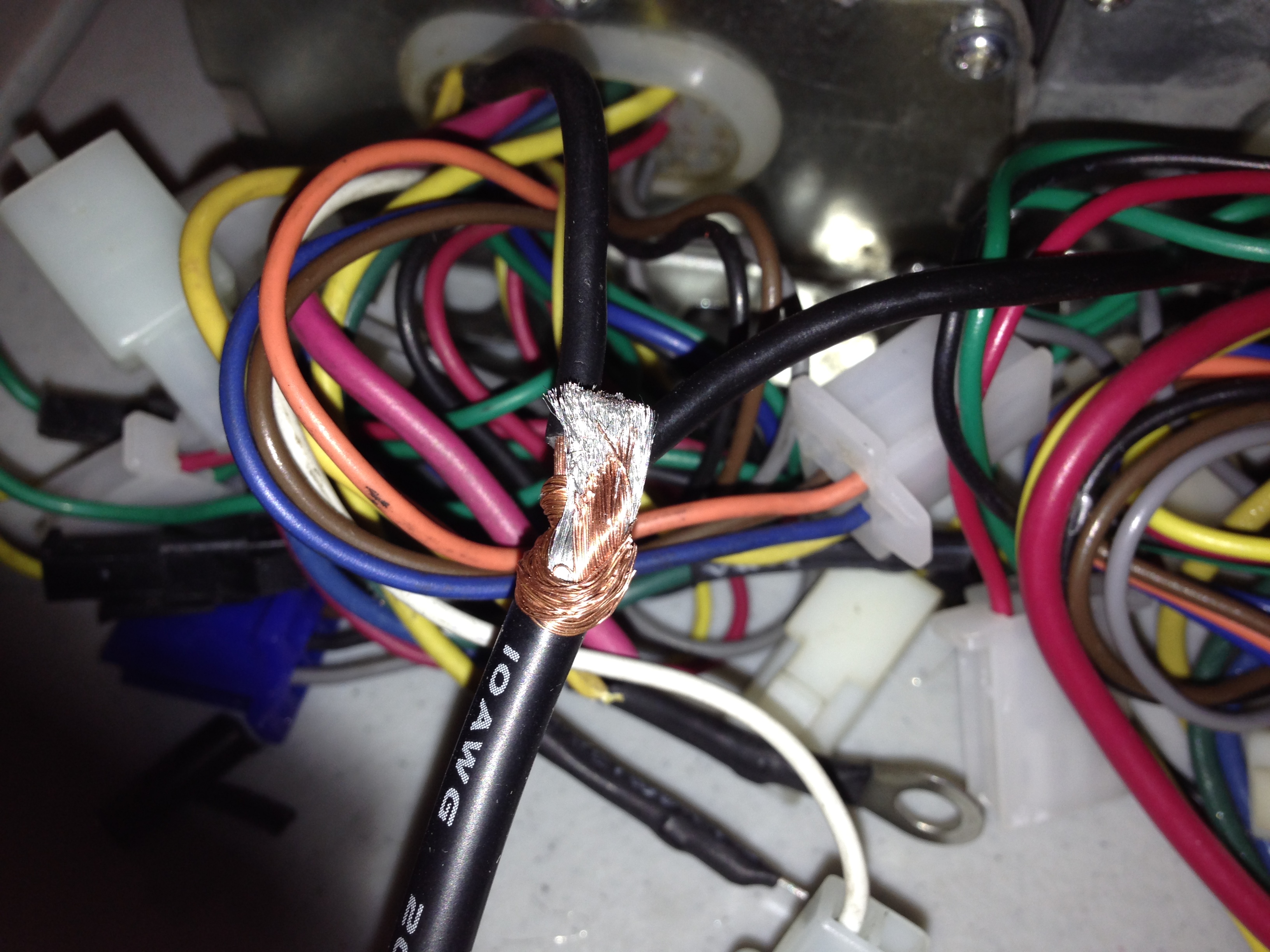
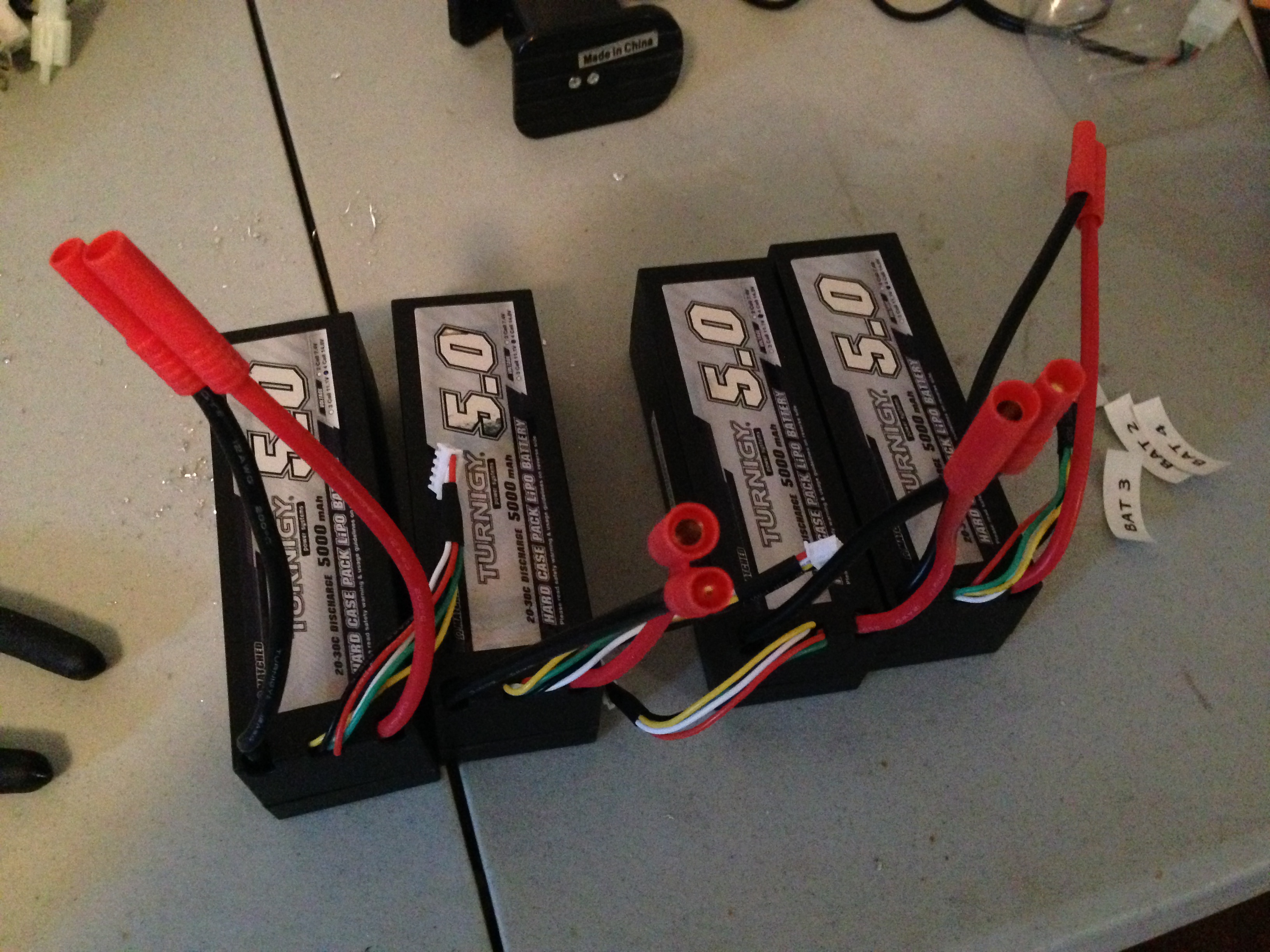
I did also make use of the handy connectors Hobbyking has developed to form parallel packs for their batteries. This makes it a lot easier to recharge and repurpose the batteries without having to resolver components.
The connections are pretty straightforward because the motor controllers act like a hub. The power, motors and throttle all connect directly to them. Just make sure to add the switch and fuse between the controllers and batteries.
Also important are the lots of additional connectors that come with the controllers. Just cut them off. If you don’t know what it does just cut it off. The controllers come with a sheet explaining what each connector is but in my case I left one connected and cold not figure out why the go cart was simply spinning full speed ahead without the throttle being engaged.
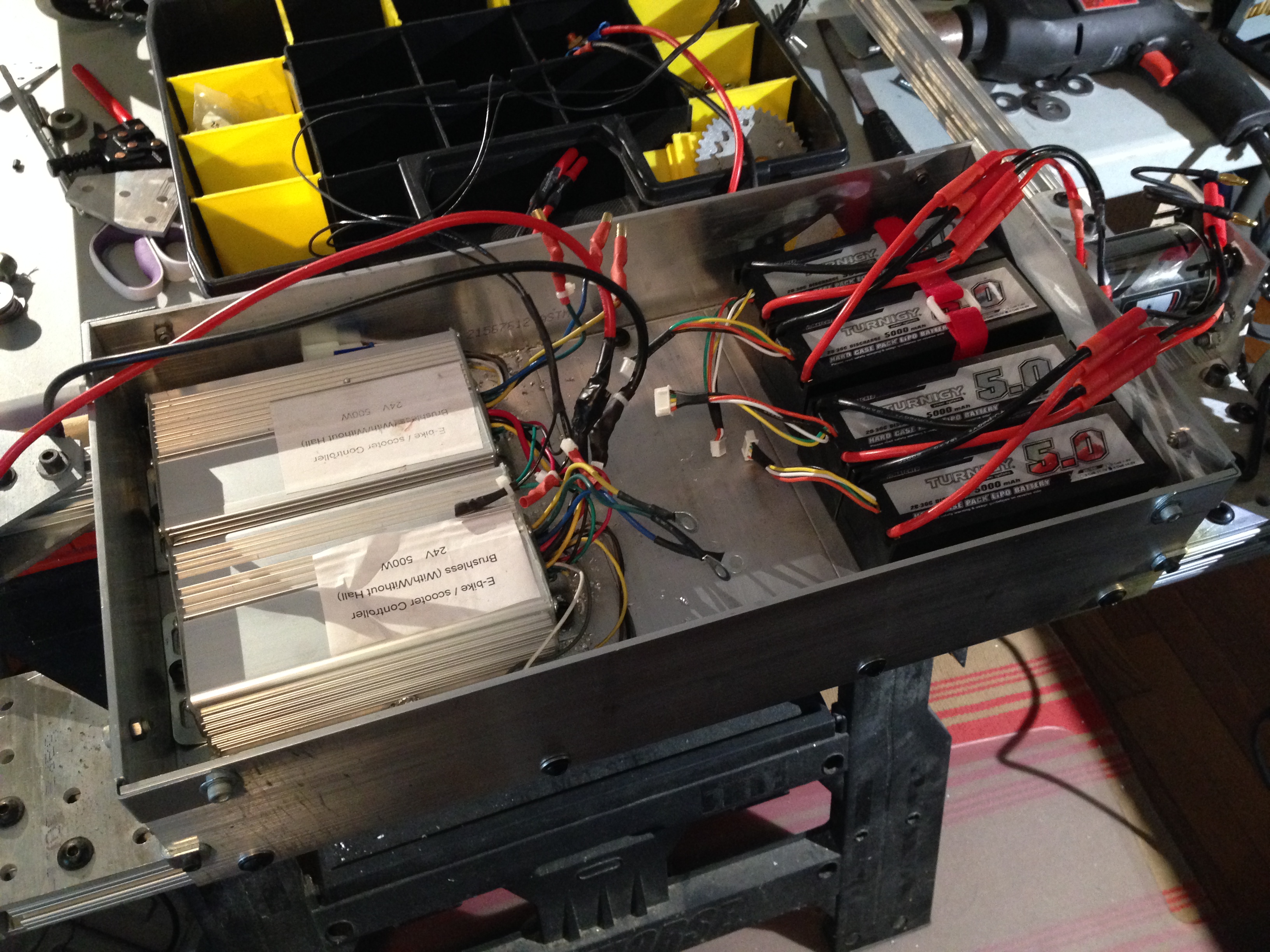
 Here you can see the battery packs joined together in parallel to form a 8S2P pack. On the opposite side are the motor controllers.
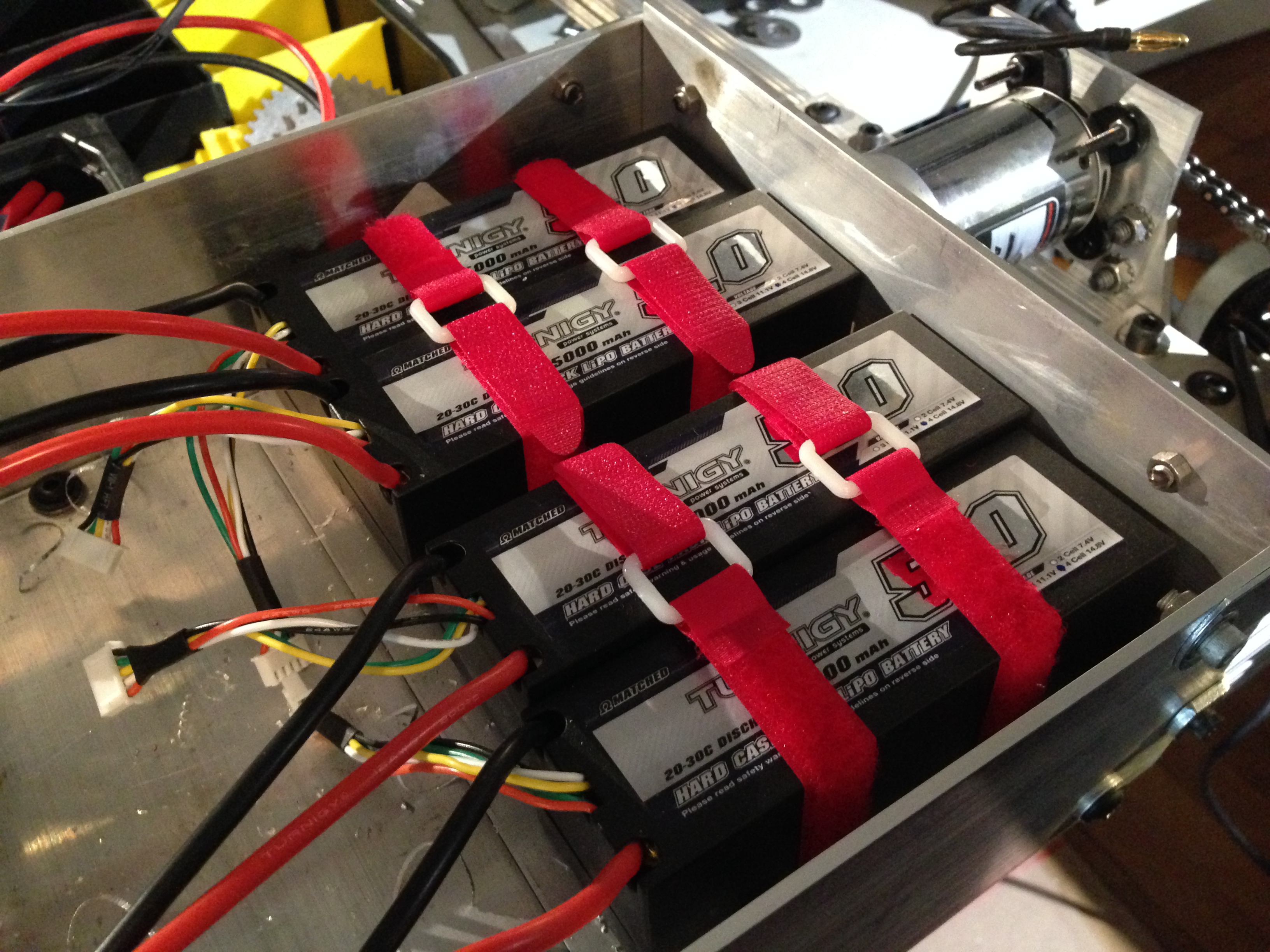
It helps to fasten the packs down with some velcro straps instead of bouncing around. The downside to an all metal case like this is that if you leave anything exposed there is the chance of a short so I covered everything in electrical tape and/or shrink tube.
And the fuse on the outside of the case. It makes for easy replacement incase I blow a fuse. At some point I need to provide a cover for the motors so that crud from the road does not get inside them.


Pingback: Electric Go-Kart Made From Off The Shelf Components
Pingback: Electric Go-Kart Made From Off The Shelf Components | Hack The Planet
Pingback: Heute basteln wir ein Elektro Go Cart. | Autesion
Wow what a great project! Looks like a lot of fun and heartbleed 🙂
What is planed next?
Hi John. I am hoping to make a go cart v2 soon. Please vote for my go cart
http://www.bocabearings.com/innovation-contest/ContestantDetails.aspx?ProjectID=110
I see you don’t monetize your page, don’t waste your
traffic, you can earn extra bucks every month because you’ve got hi quality content.
If you want to know how to make extra bucks, search for: Boorfe’s
tips best adsense alternative