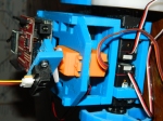
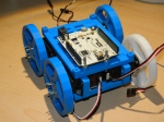
The 3D printed rover that I have been working on, on and off of, due to college applications is finally operational.
The video can also be seen here.
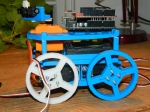
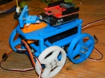
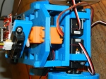
To recap a few things before I go on to the next part, the rover is powered by 4x continuous rotation servos and communicates with the computer by means of Xbee and a program running on the computer called ZTerm. The part are all printed and designed by me and what makes them unique is the fact that the 3D printed parts are held together by friction. The wheels and motors are bolted on, but that is it, there is no glue, tape or anything bonding the robot together.
What I am planning to do in the future is add an Ultrasonic and IR range finding sensors (long and short range respectively) so that the rover can navigate around while the driver cannot see it. Simultaneously it will build a 2D landscape as if you were looking at the surroundings from above by taking that data collected from the sensors (and a compass sensor for direction) as a Python program plots the points.
Here is the code that runs on the rover:
The controls are “wasd” and “e” to stop.
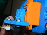
If you think that this is neat please pass it on. I would love to hear any suggestions that people have for improving it. I apologize for the video quality. This is the only camera that I have on hand at the moment but I will try and get my hands on another for a better quality video in the next day or so. Please refer to the photos here for better detail.
I will also upload the 3D files if you would like to print your own copy. It took me about 22 hours to print everything on the “Fine” setting.
#include
Servo S1; //right drive train
Servo S2; //right drive train
Servo S3; //left drive train
Servo S4; //left drive train

int the_direction = 0;

void setup(){
S1.attach(11);
S2.attach(6);
S3.attach(5);
S4.attach(3);
Serial.begin(9600);
}

void loop (){
while(Serial.available()){ //is there anything to read?
char recieved_byte = Serial.read();

if (recieved_byte == 's') {
the_direction = 1;
}
if (recieved_byte == 'w') {
the_direction = 2;
}
if (recieved_byte == 'a') {
the_direction = 3;
}
if (recieved_byte == 'd') {
the_direction = 4;
}
if (recieved_byte == 'e') {
the_direction = 5;
}

if (the_direction == 1) {
forward();
}
if (the_direction == 2) {
backward();
}
if (the_direction == 3) {
left();
}
if (the_direction == 4) {
right();
}
if (the_direction == 5) {
stopp();
}

Serial.println(the_direction);
Serial.println(recieved_byte);
}
}

void forward(){
Serial.println("forward");
S1.write(180);
S2.write(180);
S3.write(0);
S4.write(0);
}

void backward(){
Serial.println("backward");
S1.write(0);
S2.write(0);
S3.write(180);
S4.write(180);
}

void left(){
Serial.println("left");
S1.write(180);
S2.write(180);
S3.write(180);
S4.write(180);
}

void right(){
Serial.println("right");
S1.write(0);
S2.write(0);
S3.write(0);
S4.write(0);
}

void stopp(){
Serial.println("stop");
S1.write(90);
S2.write(90);
S3.write(90);
S4.write(90);
}
1/13/2013
WE HAVE MOVEMENT!
First movement from BenR on Vimeo.
Recently I was able to convince Instructables to sponsor our Robotics Club with a 3D printer. THANK YOU INSTRUCTABLES! We have been busy printing ever since. Despite the long wait for prints we have completely fallen in love with the printer.
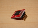
As a second term senior I have found that I have some additional time on my hands and needed a new project. What I came up with was a 3D printer cart powered by 4x continuous rotation servos that would be remotely controlled with Xbee. The attached sensors are a compass sensor and IR range finder. The point is to be able to remotely drive the cart into a room and have it create a 2D map of the room and then send that data back to the controller wherever their computer is.
At this point I have run test scripts with the Xbee and compass sensor. Finished printing all of the parts and soldered header pins onto everything. Now I need to put all of the parts together and program it.

To clarify a few things in the schematic. The Xbee will be connected to the Arduino with Sparkfun’s Xbee shield. There will also be some additional button/LED/switches in the final project, but I did not feel that it was worth cluttering the schematic up to put them in.
The majority of the programming will take place using Python and Tkinter for the interface. I hope to do as much of the number crunching on the computer instead of on the Arduino to keep the rover constantly moving instead of pausing to do calculations.
The general idea is to have the computer send a command “drive forward 10cm” which the rover then does. Then the computer says “ping” and the rover spins the servo with attached ultrasonic sensor and takes distance readings at 0′,30′,60’…180′ and then sends that back to the computer. The computer then with some geometry plots those coordinates and sees that there is a wall 15cm ahead so it sends “turn 90 degrees”. The rover does this with the help of the compass sensor and continues on.
1/10/2013


1/2/2013


12/20/2012


Pingback: 3D printed rover – first controlled movement | Built By Ben
I must say you have hi quality articles here. Your posts should go viral.
You need initial traffic only. How to get massive traffic?
Search for: Murgrabia’s tools go viral